Module QJ71C24N thuộc dòng Q-Series của Mitsubishi, hỗ trợ các giao thức truyền thông nối tiếp qua chuẩn RS232(CH1 ), RS422/485(CH2). Module này có khả năng hoạt động ở nhiều chế độ, trong đó Non-Procedural Mode cho phép truyền dữ liệu ở dạng chuổi ( Serial ) dành cho các giao thức tự phát triển không dựa trên các giao thức tiêu chuẩn như Modbus…
Ứng dụng phổ biến:
Kết nối với cảm biến, Camera, Máy In …
Gửi/nhận dữ liệu từ các thiết bị đầu cuối khác qua cổng nối tiếp.
Bài viết dưới đây tôi sẽ hướng dẫn cách sử dụng QJ71C24N để thực hiện truyền thông giữa PLC Q03UDVCPU với một bộ cảm biến Loadcell, giao thức truyền thông Non-Procedural.
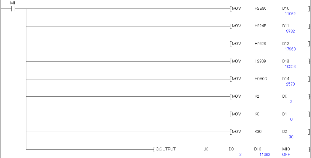
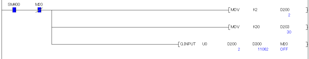
Chương trình hoạt động như sau: 1. PLC gủi 1 lệnh có cú pháp : 6+N”(F9)<CRC> bằng lệnh G.OUTPUT 2. Loadcell sẽ gủi trả lại thông tin, PLC nhận thông tin này bằng lệnh G.INPUT
2. Cách kết nối phần cứng
Module Nguồn Điện Q61P
Module Q03UDVCPU
Module QJ71C24N ( I/O 00)
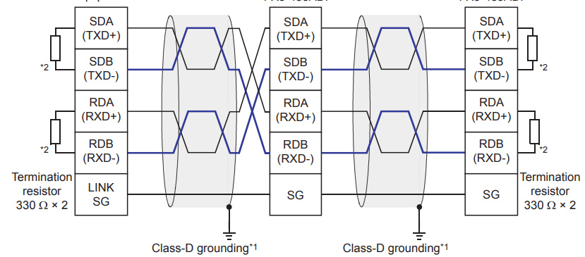
Trên Module QJ71C24N có 2 kênh truyền thông CH1 : RS232, CH2 : RS422/485. Trong trường hợp này chúng ta dùng CH2 Sơ đồ nối dây giữa QJ71C24N với Loadcell như sau:
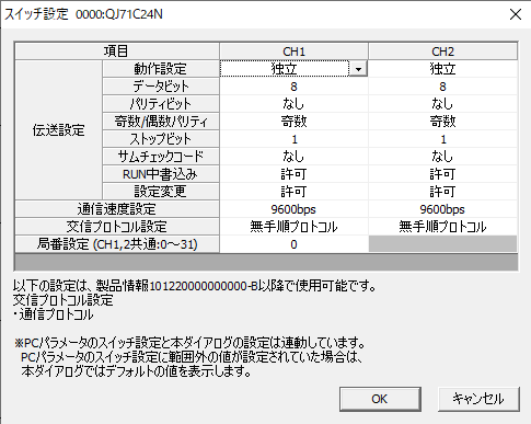
3. Cấu hình thông số truyền thông trên phần mềm
Mở phần mềm GX Works2.
Vào mục Project >>> Intelligent Function Unit >>> Add New Unit>>>thêm module QJ71C24N vào danh sách module.
Cấu hình các thông số truyền thông:
Chọn chế độ Non-Procedural.
Thiết lập tốc độ truyền (Baud Rate), bit dữ liệu, bit dừng, và chẵn lẻ.
Cấu hình cổng giao tiếp (RS232, RS422 hoặc RS485).
Trong quá trình truyền thông, có thể xảy ra một số lỗi như:
Timeout: Không nhận được phản hồi từ thiết bị ngoại vi.
Dữ liệu không hợp lệ: Sai lệch cấu hình tốc độ truyền hoặc định dạng dữ liệu.
Bạn có thể sử dụng các cờ trạng thái và vùng buffer chẩn đoán của module để xác định nguyên nhân và xử lý lỗi.
Các cờ lỗi quan trọng:
Error Code (Buffer 0300H): Mã lỗi báo hiệu nguyên nhân truyền thông thất bại.
Timeout Flag: Cờ báo hiệu hết thời gian chờ phản hồi.
1. Introduction to the QJ71C24N Module
The QJ71C24N module is part of Mitsubishi’s Q-Series, supporting serial communication protocols via RS232 (CH1) and RS422/485 (CH2) interfaces. This module operates in multiple modes, including Non-Procedural Mode, which allows data to be transmitted as raw serial strings. This mode is suitable for custom communication protocols that are not based on standard protocols like Modbus.
Common applications:
Connecting to sensors, cameras, printers, etc.
Sending and receiving data from other terminal devices through serial ports.
In this guide, I will demonstrate how to use the QJ71C24N module to establish communication between a Q03UDVCPU PLC and a load cell sensor using the Non-Procedural communication protocol.
Program flow:
The PLC sends a command with the syntax: 6+N”(F9)<CRC> using the G.OUTPUT instruction.
The load cell returns data, which the PLC receives using the G.INPUTinstruction.
2. Hardware Connection Setup
The following components are required:
Q61P Power Supply Module
Q03UDVCPU Module
QJ71C24N Module (I/O Address: 00)
The QJ71C24N module has two communication channels: CH1 (RS232) and CH2 (RS422/485). In this case, we will use CH2.
Wiring diagram: The wiring setup between the QJ71C24N module and the load cell sensor is illustrated as follows:
3. Communication Parameter Configuration
Open the GX Works2 software.
Navigate to Project >>> Intelligent Function Unit >>> Add New Unit, and add the QJ71C24N module to the module list.
Configure the communication parameters:
Select the Non-Procedural mode.
Set the baud rate, data bits, stop bits, and parity bits according to your device specifications.
Configure the communication port (RS232, RS422, or RS485).
For detailed configuration instructions, refer to the guide linked here:
4. Using Buffer Memory for Data Transmission and Reception
The QJ71C24N module uses buffer memory addresses to store transmitted and received data. Key buffer memory addresses include:
Buffer 0000H: Data transmission buffer.
Buffer 0100H: Data reception buffer.
Buffer 0200H: Status flags, such as start transmission, transmission complete, and data reception status.
Understanding these buffer addresses is crucial for managing data within the control program.
5. Writing a Ladder Program for Non-Procedural Communication
Program explanation:
The PLC sends the command 6+N”(F9) as a hexadecimal string: 36 2B 4E 22 28 46 39 29 using the G.OUTPUT instruction.
The load cell responds with data, which the PLC captures using the G.INPUT instruction.
For more details on communication instructions, refer to this guide: Here !
6. Notes on Configuration and Programming
During communication, some common errors may occur, such as:
Timeout: No response received from the external device.
Invalid Data: Data format or transmission speed mismatches between devices.
You can diagnose and troubleshoot errors by monitoring the module’s status flags and buffer memory.
Key error indicators:
Error Code (Buffer 0300H): Indicates the cause of communication failure.
Timeout Flag: Signals that the response time limit has been exceeded.
Properly handling these errors will help ensure reliable communication in your system.