
English is below …
Điều khiển LED dán tiếp thông qua Serial Monitor
Bài viết này chia sẻ cách mình thiết lập giao tiếp RS485 giữa hai board ESP32 DEVKIT V1 thông qua module MAX485, trong đó:
- Board A: nhận lệnh 1 hoặc 0 từ Serial Monitor
- Board B: nhận dữ liệu qua RS485 và bật / tắt LED
Không sử dụng nút bấm IO, không Modbus – chỉ tập trung kiểm tra đường truyền RS485 + điều khiển cơ bản.
1. Mục tiêu của bài test
- Xác nhận:
- ESP32 hoạt động ổn định
- UART2 hoạt động đúng
- Module RS485 (MAX485) hoạt động đúng
- Đường A/B/GND được nối chính xác
- Làm nền để sau này:
- Mở rộng sang Modbus RTU
- Xây dựng jig test cho sản xuất
2. Nguyên lý hoạt động
PC (Serial Monitor)
        |
      USB
        |
Board A (ESP32)
  đọc '1' / '0'
        |
      RS485
        |
Board B (ESP32)
  bật / tắt LED
- Người dùng gõ
1hoặc0trên Serial Monitor - Board A gửi ký tự đó qua RS485
- Board B nhận và điều khiển LED
3. Phần cứng sử dụng
- 2 × ESP32 DEVKIT V1
- 2 × Module RS485 (MAX485 hoặc loại tương thích)
- Dây nối A/B/GND
- Cáp USB cho mỗi board
4. Sơ đồ nối dây
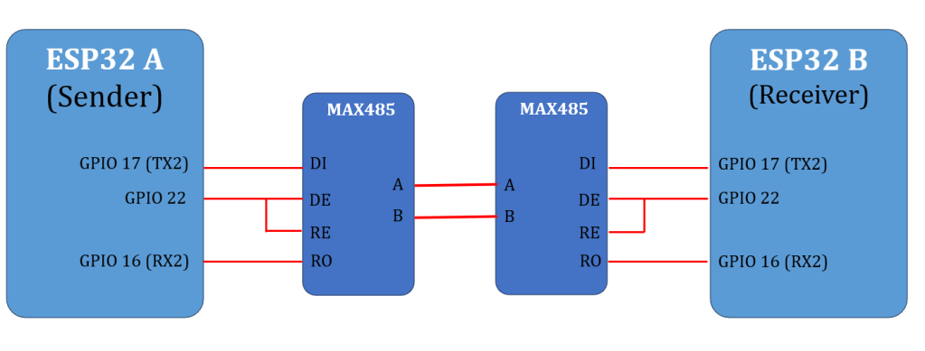
4.1. ESP32 ↔ Module RS485 (áp dụng cho cả hai board)
| ESP32 | MAX485 |
|---|---|
| GPIO17 (TX2) | DI |
| GPIO16 (RX2) | RO |
| GPIO22 | DE & /RE (nối chung) |
| 5V hoặc 3V3 | VCC |
| GND | GND |
DIR = HIGH → phát (TX)
DIR = LOW → nhận (RX)
4.2. Giữa hai module RS485
- A ↔ A
- B ↔ B
- GND ↔ GND (bắt buộc)
Nếu không nhận dữ liệu, hãy thử đảo A/B ở một đầu.
Lưu ý:
Nếu module MAX485 chạy 5V, chân RO có thể ra 5V → ESP32 không chịu được 5V ở RX.
Nên dùng module RS485 3.3V hoặc thêm chia áp cho chân RO.
5. Chương trình cho Board A
(Serial → RS485)
- Gõ
1→ gửi'1' - Gõ
0→ gửi'0'
// A_serial_to_rs485.ino
#include <Arduino.h>

#define TX_PIN   17
#define RX_PIN   16
#define DIR_PIN  22

HardwareSerial rs485(2);

static void rs485SendByte(uint8_t b) {
  digitalWrite(DIR_PIN, HIGH);
  delayMicroseconds(200);
  rs485.write(&b, 1);
  rs485.flush();
  delayMicroseconds(200);
  digitalWrite(DIR_PIN, LOW);
}

void setup() {
  Serial.begin(115200);
  delay(200);
  Serial.println("\n[A] Serial -> RS485 Sender");
  Serial.println("[A] Type '1' = LED ON, '0' = LED OFF");

  rs485.begin(9600, SERIAL_8N1, RX_PIN, TX_PIN);
  pinMode(DIR_PIN, OUTPUT);
  digitalWrite(DIR_PIN, LOW);
}

void loop() {
  if (Serial.available()) {
    char c = Serial.read();

    if (c == '1' || c == '0') {
      rs485SendByte(c);
      Serial.printf("[A] Send '%c'\n", c);
    }
  }
}
6. Chương trình cho Board B
(RS485 → LED)
- Nhận
'1'→ LED ON - Nhận
'0'→ LED OFF
LED mặc định là GPIO2 (LED on-board ESP32 DEVKIT V1).
// B_rs485_to_led.ino
#include <Arduino.h>

#define TX_PIN   17
#define RX_PIN   16
#define DIR_PIN  22
#define LED_PIN  2

HardwareSerial rs485(2);

void setup() {
  Serial.begin(115200);
  delay(200);
  Serial.println("\n[B] RS485 Receiver -> LED");

  pinMode(LED_PIN, OUTPUT);
  digitalWrite(LED_PIN, LOW);

  rs485.begin(9600, SERIAL_8N1, RX_PIN, TX_PIN);
  pinMode(DIR_PIN, OUTPUT);
  digitalWrite(DIR_PIN, LOW); // luôn ở RX
}

void loop() {
  while (rs485.available()) {
    char c = rs485.read();
    Serial.printf("[B] RX '%c'\n", c);

    if (c == '1') {
      digitalWrite(LED_PIN, HIGH);
      Serial.println("[B] LED ON");
    } else if (c == '0') {
      digitalWrite(LED_PIN, LOW);
      Serial.println("[B] LED OFF");
    }
  }
}
7. Cách test nhanh
- Nạp code Board A và Board B
- Mở Serial Monitor của Board A
- Baud:
115200 - Line ending:
No line ending
- Baud:
- Gõ:
1→ LED board B (GPIO2) sáng0→ LED board B (GPIO2) tắt
8. Các lỗi thường gặp và cách xử lý
| Hiện tượng | Nguyên nhân |
|---|---|
| Không nhận dữ liệu | Chưa nối GND chung |
| Không có phản hồi | Đấu nhầm A/B |
| RX không nhận | RO = 5V từ MAX485 |
| ESP reset | Nguồn VIN không ổn định |
Chúc các bạn thực hành thành công!
RS485 Communication Between Two ESP32 Boards Using MAX485
Controlling an LED via Serial Monitor
When developing hardware or preparing a production test, it is very useful to have a simple, visual, and easy-to-debug RS485 test.
This article demonstrates how to establish RS485 communication between two ESP32 DEVKIT V1 boards using MAX485 modules, where:
- Board A receives commands (
1or0) from the Serial Monitor - Board B receives data via RS485 and turns an LED ON or OFF
No GPIO buttons and no Modbus are used in this example.
The goal is to verify basic RS485 communication and hardware wiring.
1. Purpose of This Test
This test is designed to confirm:
- ESP32 boards are working correctly
- UART2 on ESP32 is functional
- MAX485 RS485 transceivers operate correctly
- RS485 wiring (A / B / GND) is correct
- Direction control (DE / RE) is handled properly
This setup can later be extended to:
- Modbus RTU communication
- Automated production test jigs
- More complex protocols with acknowledgments
2. System Overview
PC (Serial Monitor)
        |
      USB
        |
ESP32 Board A
  reads '1' or '0'
        |
      RS485
        |
ESP32 Board B
  LED ON / OFF
- The user types
1or0in the Serial Monitor - Board A sends this character over RS485
- Board B receives it and controls an LED
3. Hardware Components
- 2 × ESP32 DEVKIT V1 boards
- 2 × RS485 modules (MAX485 or compatible)
- RS485 wiring (A / B / GND)
- USB cables for programming and monitoring
4. Wiring Connections
4.1 ESP32 ↔ RS485 Module (Both Boards)
| ESP32 Pin | MAX485 Pin | Description |
|---|---|---|
| GPIO17 (TX2) | DI | UART TX to RS485 |
| GPIO16 (RX2) | RO | RS485 to UART RX |
| GPIO22 | DE & /RE (tied together) | Direction control |
| 5V or 3.3V | VCC | Power for MAX485 |
| GND | GND | Common ground |
Direction logic:
- GPIO22 = HIGH → Transmit
- GPIO22 = LOW → Receive
4.2 RS485 Bus Between Modules
- A ↔ A
- B ↔ B
- GND ↔ GND (mandatory)
If communication does not work, try swapping A and B on one side.
Important note about voltage levels
Many MAX485 modules operate at 5V, and their RO output may be 5V.
ESP32 GPIO pins are not 5V tolerant.
Recommended solutions:
- Use a 3.3V RS485 transceiver (MAX3485, SP3485, etc.)
- Or add a voltage divider between RO and ESP32 RX
5. Code for Board A
Serial → RS485 Sender
- Type
1→ send'1' - Type
0→ send'0'
6. Code for Board B
RS485 → LED Receiver
- Receive
'1'→ LED ON - Receive
'0'→ LED OFF
The onboard LED on ESP32 DEVKIT V1 is typically connected to GPIO2.
7. How to Test
- Upload the Sender code to Board A
- Upload the Receiver code to Board B
- Open Serial Monitor for Board A
- Baud rate: 115200
- Line ending: No line ending
- Type:
1→ LED on Board B turns ON0→ LED on Board B turns OFF
8. Common Problems and Solutions
| Issue | Possible Cause |
|---|---|
| No response | GND not connected |
| No data received | A/B lines swapped |
| RX not working | RO output is 5V |
| ESP32 resets | Unstable VIN power |
| LED does not light | Wrong LED pin |
Good luck !
