Enlish is below
Giới thiệu
Khi làm việc với hệ thống Servo Mitsubishi, nhiều kỹ sư thường cho rằng việc đọc các dữ liệu nội bộ của Servo như:
- Tốc độ động cơ
- Số xung Encoder
- Vị trí tuyệt đối
- Alarm
bắt buộc phải sử dụng:
- MR Configurator
- Module truyền thông chuyên dụng
- CC-Link
- SSCNET
Tuy nhiên trong quá trình thực hiện dự án sử dụng Servo HF-KP23B và Driver MR-J3-20A1, tôi đã thử nghiệm thành công việc đọc dữ liệu trực tiếp từ Driver bằng PLC FX5U thông qua cổng CN3.
Toàn bộ hệ thống chỉ sử dụng:
- FX5U-32MR/ES
- FX5-485-BD
- MR-J3-20A1
- HF-KP23B
không cần máy tính và không cần phần mềm MR Configurator.
Mục tiêu
Đọc trực tiếp các thông tin nội bộ của Driver:
- Tốc độ động cơ
- Feedback Pulse
- Absolute Position
- Alarm hiện tại
- Trạng thái Input/Output
Nguyên lý hoạt động
- Driver MR-J3 cung cấp giao thức truyền thông ASCII thông qua cổng CN3.
- PLC gửi lệnh dưới dạng chuỗi ASCII.
- Driver phân tích lệnh và trả về dữ liệu theo đúng định dạng của MELSERVO Communication Protocol.
Ví dụ lệnh đọc tốc độ động cơ:
ASCII
SOH 1 01 STX 81 ETX 00
HEX
01 31 30 31 02 38 31 03 30 30
Sau khi nhận lệnh, Driver trả về:
ASCII
1A00000097DD9
Trong đó:
A
là mã phản hồi thành công.
Điều này chứng minh PLC đã giao tiếp được với Driver.
Kết quả
Qua thử nghiệm thực tế:
✓ FX5U giao tiếp được với MR-J3 qua CN3
✓ FX5-485-BD sử dụng được cho mục đích này
✓ Đọc được dữ liệu nội bộ của Servo
✓ Không cần MR Configurator
✓ Không cần mạng Servo chuyên dụng
Ý nghĩa thực tế
Giải pháp này đặc biệt hữu ích cho:
- Hệ thống giám sát Servo
- Ghi log dữ liệu vận hành
- Chẩn đoán lỗi từ PLC
- Hiển thị trạng thái Servo trên HMI
- Xây dựng hệ thống bảo trì dự đoán (Predictive Maintenance)
với chi phí rất thấp vì tận dụng phần cứng sẵn có của FX5U.
Đây là một hướng tiếp cận đáng cân nhắc khi cần lấy dữ liệu từ Servo Mitsubishi nhưng không muốn đầu tư thêm các mạng truyền thông chuyên dụng.
Content by Enlish
Reading Servo Speed and Position from MR-J3-20A1 Using FX5U Non-Protocol Communication
Introduction
When working with Mitsubishi servo systems, many engineers assume that reading internal servo data such as motor speed, feedback pulse count, absolute position, or alarm information requires either:
- MR Configurator software
- A dedicated communication module
- CC-Link communication
- SSCNET communication
However, during a recent project involving an HF-KP23B servo motor and MR-J3-20A1 servo amplifier, I successfully established direct communication between an FX5U PLC and the servo amplifier using only:
- FX5U-32MR/ES
- FX5-485-BD communication board
- MR-J3-20A1 servo amplifier
- CN3 communication port
without any additional gateway or PC software.
This article documents the complete process.
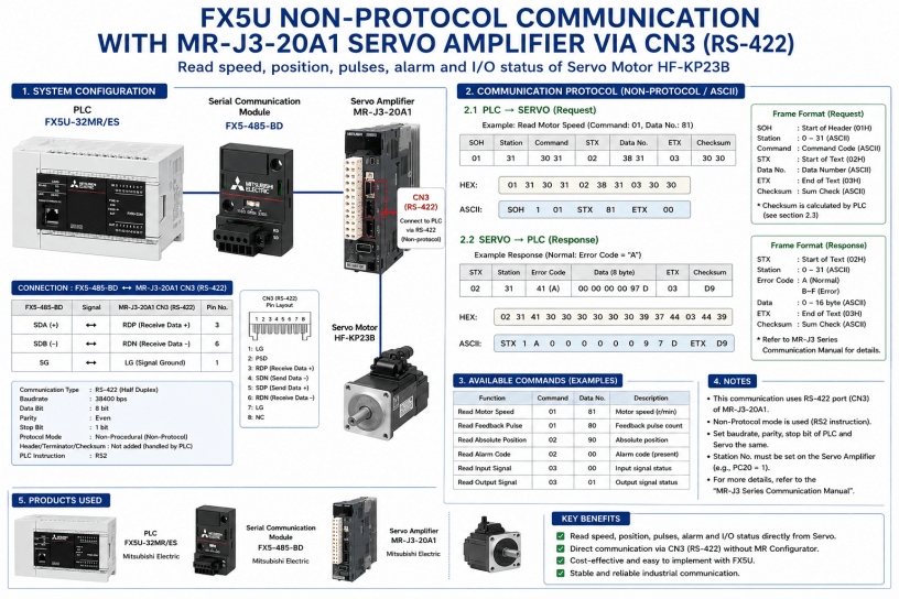
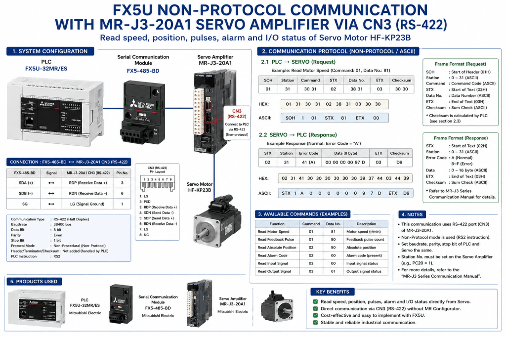
System Configuration
The hardware configuration is shown below:
FX5U-32MR/ES
↓
FX5-485-BD
↓
MR-J3-20A1 (CN3 RS-422)
↓
HF-KP23B Servo Motor
The objective was to retrieve internal servo information directly from the amplifier.
Available information includes:
- Motor Speed (r/min)
- Feedback Pulse Count
- Absolute Position
- Current Alarm Code
- Input Signal Status
- Output Signal Status
Understanding the CN3 Communication Port
MR-J3 servo amplifiers provide a communication interface on CN3.
The communication protocol is documented in the Mitsubishi MELSERVO Communication Protocol Manual.
Unlike Modbus RTU, the protocol is ASCII-based and uses the following control characters:
| Symbol | Hex |
|---|---|
| SOH | 01H |
| STX | 02H |
| ETX | 03H |
Communication follows a request-response structure.
PLC sends a command.
Servo amplifier returns the requested data.
PLC Communication Settings
FX5-485-BD was configured in Non-Procedural Mode.
Communication parameters:
| Item | Setting |
|---|---|
| Baud Rate | 38400 bps |
| Data Length | 8 bit |
| Parity | Even |
| Stop Bit | 1 bit |
| Protocol | Non-Procedural |
| Header | Not Added |
| Terminator | Not Added |
| Checksum | Not Added |
The PLC handles all protocol formatting manually.
Wiring Between FX5-485-BD and CN3
The following wiring was tested successfully:
| FX5-485-BD | MR-J3 CN3 |
|---|---|
| SDA (+) | RDP (Pin 3) |
| SDB (-) | RDN (Pin 6) |
| SG | LG (Pin 1) |
Communication was established without additional converters.
Building the Communication Frame
To read motor speed, the servo protocol requires:
Command:
01
Data Number:
81
The complete request frame becomes:
ASCII
SOH 1 01 STX 81 ETX 00
HEX
01 31 30 31 02 38 31 03 30 30
In PLC memory:
| Register | Value |
|---|---|
| D100 | H0131 |
| D101 | H3031 |
| D102 | H0238 |
| D103 | H3103 |
| D104 | H3030 |
The RS2 instruction transmits these ten bytes directly to the servo amplifier.
Servo Response
After transmission, the servo amplifier returned:
HEX
02 31 41 30 30 30 30 30 30 39 37 44 03 44 39
ASCII
1A00000097DD9
Breaking down the frame:
| Field | Meaning |
|---|---|
| 02 | STX |
| 31 | Station 1 |
| 41 | A (Normal Response) |
| 00000097D | Data |
| 03 | ETX |
| D9 | Checksum |
The important point is the error code:
A
which indicates:
Normal Operation
The servo amplifier accepted the command and returned valid data.
Why This Result Matters
Before testing, there was uncertainty regarding:
- RS-422 compatibility
- FX5-485-BD support
- CN3 communication access
- Requirement for dedicated hardware
The successful response proves that:
✓ FX5U can communicate directly with MR-J3 through CN3.
✓ Servo internal data can be accessed without MR Configurator.
✓ Standard Non-Protocol communication is sufficient.
✓ No dedicated servo network is required.
Available Commands
Some useful commands include:
| Function | Command | Data No |
|---|---|---|
| Motor Speed | 01 | 81 |
| Feedback Pulse | 01 | 80 |
| Absolute Position | 02 | 90 |
| Alarm Code | 02 | 00 |
| Input Status | 03 | 00 |
| Output Status | 03 | 01 |
This allows the PLC to monitor the servo amplifier directly.
Conclusion
This experiment demonstrates that Mitsubishi FX5U PLCs can successfully communicate with MR-J3 servo amplifiers using the CN3 communication port and standard Non-Protocol communication.
For applications requiring servo monitoring, diagnostics, data logging, or machine condition analysis, this approach provides a simple and low-cost solution without relying on dedicated motion networks or PC software.
The next step is implementing PLC-side parsing routines to convert the returned ASCII data into usable numerical values such as RPM, pulse count, and absolute position for HMI display and machine diagnostics.
